Connecting everything
This is a quick write up about getting some IoT bits hooked up and talking to each other. To start playing with IoT I went with a cheap ESP32 chip from e-bay along with a basic temperature sensor. This is a list of stuff I used:
- ESP32S NodeMcu ESP32 Development Module 2.4GHz WiFi+Bluetooth Dual-Mode Antenna (spec) (129,00 CZK)
- BME-280 (90,00 CZK)
- breadboard and jumper wires (360,00 CZK)
- a basic soldering kit (500,00 CZK)
In terms cost, the entire lot came in at just over 1000 CZK (40 EUR) and I now have cables to last many projects.
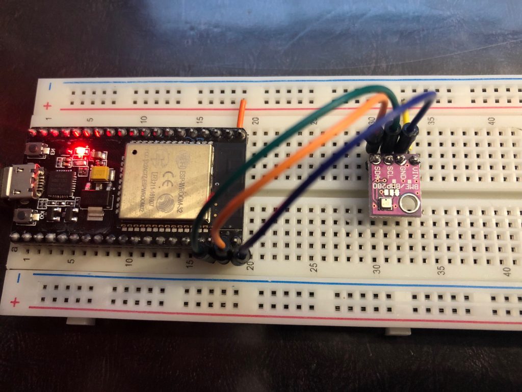
The somewhat challenging part was figuring out which data pins to connect where. This was compounded by trying to figure out whether to use ‘I2C’ or ‘SPI’ neither of which I knew anything about. I went with I2C and as it turns out if you use the defaults you only need to make sure that pin 21 and 22. It was that easy! You can also specify different pins in case those are already in use. The way to do that is to define two constants:
#define I2C_SDA 23
#define I2C_SCL 22
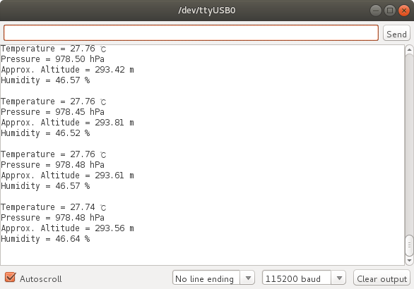
This is my src. With this mapping in place and correct baud rate setting, the Serial Monitor began showing output: